Radio Frequency Interference
Introduction
With the huge increase of wireless devices and increasing broadcast, communications systems,
and other RF sources competing for radio spectrum, the chances of radio frequency interference (RFI)
will only increase in future. This article explains how to identify, characterise,
and locate a typical interfering sources.
Categories of Interference
There are two broad categories of interference; Narrow Band and Broad Band
Narrow Band – This would include continuous wave (CW) or modulated CW signals.
Examples might include clock harmonics from digital devices, co-channel transmissions,
adjacent-channel transmissions, intermodulation products, etc. On a spectrum analyzer,
this would appear to be narrow vertical lines or slightly wider modulated vertical bands associated
with specific frequencies.
Broad band – This would primarily include switch-mode power supply harmonics,
arcing in overhead power lines (power line noise), wireless digitally-modulated systems
(such as Wi-Fi or Bluetooth), or digital television. On a spectrum analyzer,
this would appear to be broad ranges of signals or an increase in the noise floor.
Power line noise or switch-mode power supplies are the most common sources.
Types of Interference
Some of the most common types of interference are described below.
Co-Channel Interference – more than one transmitter (or digital harmonic) using,
or falling into, the same receive channel.
Adjacent-Channel Interference – a transmitter operating on an adjacent frequency whose
energy spills over into the desired receive channel.
Intermodulation-Based Interference – occurs when energy from two, or more, transmitters mix
together to produce spurious frequencies that land in the desired receive channel.
Third-order mixing products are the most common and usually, this occurs from nearby transmitters.
An example of potential intermodulation might occur in a strong signal area for FM broadcast.
Fundamental Receiver Overload – this is normally caused by a strong, nearby, transmitter simply
overloading the receiver front-end or other circuitry, causing interference or even suppression
of the normal received signal. A common example is VHF paging transmitters interfering with receivers.
Power Line Noise (PLN) – This is a relatively common broadband interference problem that is typically
caused by arcing on electric power lines and associated utility hardware. It sounds like a harsh raspy buzz
in an AM receiver. The interference can extend from very low frequencies below the AM broadcast band,
and depending on proximity to the source, into the HF spectrum. If close enough to the source,
it can extend up to the UHF spectrum.
Switch-Mode Power Supplies – Switch-mode power supplies are very common and are used for a variety of
consumer or commercial products and are a common source of broadband interference. Lighting devices,
such as the newer LED-based lights or commercial agricultural “grow” lights, are another strong source of interference.
Other Transmitters – There are several transmitter types that commonly cause RFI:
Two-Way or Land Mobile Radio – Strong interfering FM signals may result in “capture effect”,
or over-riding of the desired received signal.
Paging Transmitters – Paging transmitters are generally very powerful FM or digitally modulated transmissions
that can overload receiver Digital paging will sound very raspy, like a power saw or buzzing, and may
interfere with a wide range of receive frequencies. Fortunately, most of the VHF paging transmitters
moved to the 929/931 MHz frequency pairs, so this is not the issue it once was.
Broadcast Transmitters – Broadcast transmitter interference will have modulation characteristics similar
to their broadcasts – AM, FM, video carriers, or digital signals.
Cable Television – Signal leakage from cable television systems will generally occur on their prescribed
channel assignments. Many of these channels overlap existing over-the-air radio communications channels.
If the leaking signal is a digital channel, interference will be similar to wideband noise
(a digital cable channel is almost 6 MHz wide).
Wireless Network Interference – Interference to wireless networks (Wi-Fi, Bluetooth, etc.) is increasingly common,
and with the proliferation of mobile, household (IoT), and medical devices incorporating Wi-Fi and other wireless modes,
this issue is likely to get worse. More details on wireless interference will be found in the companion article,
Wireless Network Interference and Optimization.
Locating RFI
Simple Direction Finding (DFING)
DF Techniques – There are two primary methods for DFing.
“Pan and Scan” where you
“Pan”
a directional antenna and
“Scan” for the interfering signal, recording the direction on a map,
while keeping note of intersecting lines.
“Hot and
Cold” where an omni-directional antenna is used
while watching the signal strength. In this method, the rule of thumb is for every 6 dB change you’ve either doubled
or halved the distance to the interfering source. For example, if the signal strength was -30 dBm at one mile from
the source, traveling to within a half-mile should read about -24 dBm on the spectrum analyzer.
DF Systems – Radio Direction-Finding (RDFing) equipment can be installed into a vehicle or use a portable.
For vehicular use, there are several automated
Doppler Direction-Finding Systems available in the market.
Step Attenuator – You’ll also find a step attenuator quite valuable during theprocess of DFing.
This allows control over the signal strength indication (and receiver overload) as you approach the interference source.
The best models come in steps of 10 dB and have a range of at least 80 dB, or more.
Step attenuators may be purchased through electronics distributors, such as DigiKey, etc.
Commercial sources would include Narda Microwave, Fairview Microwave, Arrow, and others.
Locating Power Line Interference
For Low Frequency Interference – particularly power line noise (PLN) – the interference path
can include radiation due to conducted emissions along power lines. Therefore,
when using the “Hot and Cold” method you’ll need to be mindful that the radiated noise will generally
follow the route of the power lines, peaking and dipping along the route. The maximum peak usually
indicates the actual noise source. As a complication, there may be several noise sources – some possibly long distances away.
Antennas – For simply listening to power line noise, the built-in “loopstick”
antenna on an AM broadcast band radio or telescoping antenna on a shortwave radio may work well.
However, for tracking down power line noise to the source pole, and typically for DFing other interfering sources,
you’ll want to use higher frequencies. A simple three element directional Yagi, can be assembled quickly and attached to a short length of pipe and works well to receive this
type of broadband RFI.
Use of VHF Receivers – Whenever possible, you’ll generally want to use VHF or higher frequencies for DFing.
The shorter wavelengths not only help in pinpointing the source, this also make smaller handheld antennas more practical.
Locating Narrow Band Interference
For most narrow band interference sources, such as co-channel, adjacent channel,
and intermodulation interference, the recommended tool is a spectrum analyzer or a nano VNA,
as these allows you to focus on particular frequency channels or bands and see the big picture of what’s occurring.
Once the interfering signal is identified, the analyzer can then be used to DF the signal.
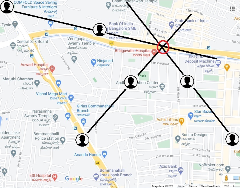
Pic: Direction Finding Model